Kalamazoo Amp Field Guide: Reverb 12 Schematic
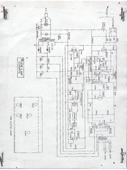
These are drawn up from various schematics, including one of my own and one someone scanned for me. I have rearranged the schematics to hopefully make them more readable. One Reverb 12 actually had two schematics, one on top of the other. One was a bit larger and more readable; the other one included a bit more data (transformer location, foot switch wiring, etc). There is at least one other version with some moderate variations in the circuitry; that one I have simply linked to without redrawing. I don't recall who originally sent me that one, but it's the one included in the Gibson Servie Manual. Scroll down for links to PostScript and higher quality images than the ones displayed on the page.
Note - I arbitrarily designated these versions 1 and 2. I have not been able to find any version information on the amps, themselves, and have no idea which came first. According to the Gibson historian (Walter Campbell), Gibson doesn't have any information on beyond schematics, either.
The largest differences in the different versions are
- tone stacks are completely different
- whether the reverb intensity control is on the drive or recovery side of the reverb circuit
- whether it has a negative feedback loop
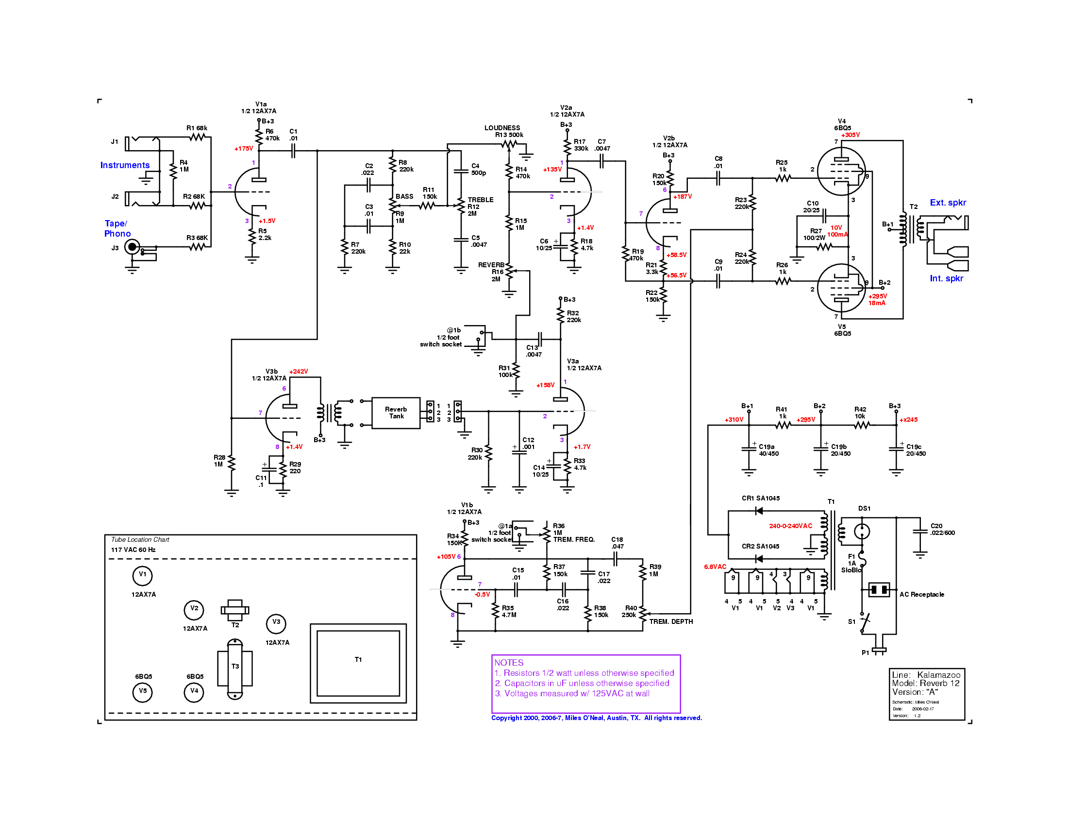
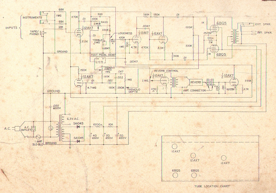
![[schematic here]](Images/KalReverb12-a-sm.gif)
Version 1
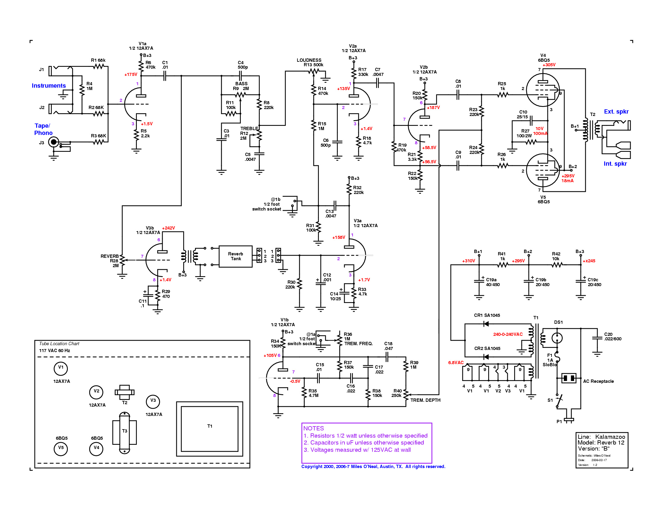
![[schematic here]](Images/KalReverb12-b-sm.gif)
Version 2
You can also get larger, more legible versions in several formats:
|
| ||||||||||||||||
The PostScript files were made with xcircuit but will work with any PS viewer or printer.
You can also see a scanned Version 1 JPEG (~185k) [540x720] or a Version 2 JPEG (~700k) [950x650].
Finally, there's a slight variation of Version 1, which I'll refer to as Version 1A. You can download a GIF at Images/BobFellows/KalR12-schem-bf.gif (100k) [2900x2100]. This incorporates a negative feedback loop from the output transformer secondary to the cathode of the second preamp tube, via a split cathode resistor setup.
The tremolo circuit operates like the best of the Fenders and other circuits, modulating the output tube grids. This yields a much better tremolo than the circuit used with the Model 2 .
The reverb comes off the output of the first preamp, along with the tone stack, and is mixed back beside the volume control.
The Kalamazoo Reverb 12 schematic is stapled to the inside of the amp's lower back panel. I prefer this to the locations used on the Model 1 and 2, as it's easier to access.
The original schematic has no copyright or patent notice. I have copyrighted my image purely to keep it available. Anyone may use this image for any non-commercial purpose, so long as they use it in its entirety, with the copyright attached, and a notice that the image is used by permission. For other uses, contact the author.
Thanks to Jeff Caruso for the scan of the original and marking up a copy of my drawing with the component values I couldn't read from the scan, to Antonio Salvatore for the fax so I could get started while awaiting a scan, to Bob Fellows for the 1A scan, and to Jerry (I never got his last name) for sending me a scan of the other version before I had my own.
Last updated: 01 September 2005
Copyright 1999,Y2K,2004 Miles O'Neal, Austin, TX. All rights reserved. Miles O'Neal <roadkills.r.us@XYZZY.gmail.com> [remove the "XYZZY." to make things work!] c/o RNN / 1705 Oak Forest Dr / Round Rock, TX / 78681-1514