Kalamazoo Amp Field Guide:
Replacing Power Supply Capacitors
DISCLAIMER:Tube amplifiers contain potentially lethal, high voltages even after they are unplugged, that may cause personal injury or death. Do not attempt to repair, modify, or work on any amplifier unless you are absolutely certain you know what you are doing.NO GUARANTEEThese mods are all things I have tried, someone I know has tried, or are recommended by people who work on amplifiers for a living. Nevertheless, if you try any of these, you assume all responsibility for anything that happens, whether the amp explodes, you get zapped, or the amp suddenly increases in value because everyone falls in love with it. The glory, the pain, whatever, they're all yours. If you can't live with that, don't mess with the amp! |
This page will attempt to guide you through replacing the power supply cap in a Kalamazoo, or other amp with multi-section caps that live inside the chassis. I'll try to get some photos or drawings up soon, but can't make any promises as to when that might happen.
A multi-section cap like that in a Kalamazoo Model One or Two is really just three caps in one package, with the negative ends tied together. The Model Twelve uses a pair of two section caps, which are essentially two caps in one package with their negative ends tied together.
Those Negative Leads
Make sure you get the polarity correct-- that the capacitor's negative and positive terminals are correctly oriented. Failure to observe polarity will almost certainly result in at least fried capacitors, and possibly other problems. All polarized capacitors have some form of markings to show polarity. Electrolytics almost always mark the negative side, at least. They may simply use plus and minus, but most, modern electrolytics have a black arrow pointing towards the negative lead. This arrow generally has negative signs embedded in it.Almost all electrolytics in guitar amps have their negative lead towards Ground. The primary exception is with fixed bias circuits, which have their positive lead grounded. Kalamazoo guitar amps all use cathode bias, so the exception doesn't apply to them.
Size Matters
The 20/10/10 cap values were common when the Kalamazoos were built, but left a lot of hum. A much better approach is to use larger caps, especially on the screen and preamp supplies. These are the 10uF caps. I prefer at least 47uF for these, and 80uF to 100uF is better. In a push-pull amp, you may want to leave the first cap size alone to keep the sag characteristics, but if you don't care, or the amp is single-ended like a Kalamazoo Model One or Two, you can use a larger cap here as well. I wouldn't go over 47uF for the first cap with the 6X4 tube rectifier; if you convert to solid state rectification, go as high as you like.
Multi-section caps in metal shells that stick
out of the chassis like a tube are similar, but
require different mounting if replaced with individual
caps.
Multi-section caps in other amps may also include
a bias cap section, which will have its positive
end connected to the negatives of the other
sections.
Some folks hunt down a replacement multi-section capacitor. Replacement in this case should be obvious. However, such caps tend to be expensive if new, or of dubious quality (if old). There is also evidence that using individual caps is a good idea, in any event.
There are several ways to mount the individual caps when you replace a multi-section cap.
Flying Lead Attachment
One of the easiest, and one many people use, is to clip the old cap out, and solder the new caps to wherever the old leads went, with the caps just hanging in the air. This turns out to be a really bad idea on a Kalamazoo, because the socket terminals are pretty weak. So vibration from playing and moving the amp is likely to break a terminal. [I've seen Kalamazoo pins break just because an original resistor lead was stressing the terminal!]If you can find caps with long enough leads, or solder extra wire (preferably insulated!) to the leads, you can find available chassis space and attach the caps with hot glue or some other form of adhesive (or cable ties and a stick-on cable tie holder, as described later). This is better than having them hang from the sockets!
Terminal Lug Attachment
 A better solution, in some ways,
involves soldering the caps to
terminal lugs. This solves the above problem.
But it requires adding a new terminal strip,
or replacing an old strip or two with bigger
ones. And you have to be careful with lead
dress (where the wires go) or you add hum.
It's not as critical as most lead dress, but
it is an issue. (Not that this is a bad thing;
you'll need to learn lead dress sooner or later!)
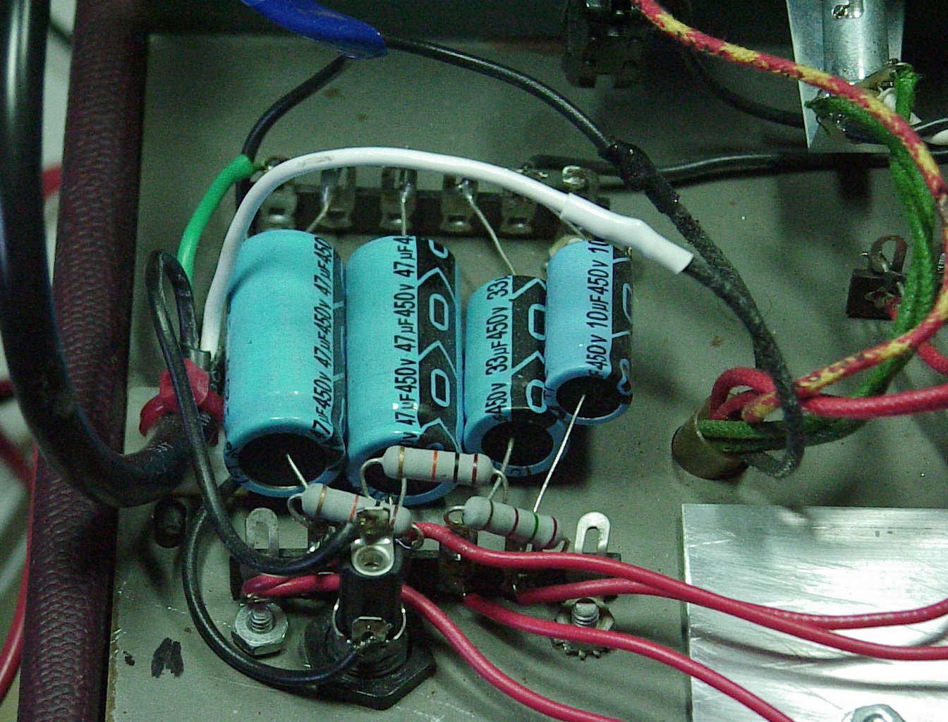
In the photo at the left, there's an extra cap. The 10uF
and 33uF caps, along with the resistor between
them, form a pi filter before the plate supply.
This is in a prototype amp that's essentially
a heavily hot-rodder Model One. Note the
repositioned fuse holder; make sure the resistor
bodies don't touch the fuse holder leads, or
you may get a resistor body punch through
complete with fireworks. (Guess how I know.)
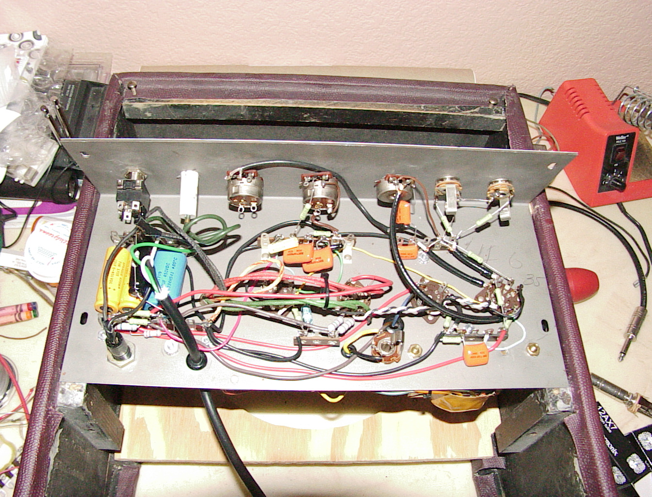
The photo on the right shows a stock Kalamazoo
Model Two circuit rebuilt with customer
supplied components.
The extra cap and resistor across the top of the PS
caps is part of the DC bias circuit added to the
filament wiring to reduce hum.
A better solution, in some ways,
involves soldering the caps to
terminal lugs. This solves the above problem.
But it requires adding a new terminal strip,
or replacing an old strip or two with bigger
ones. And you have to be careful with lead
dress (where the wires go) or you add hum.
It's not as critical as most lead dress, but
it is an issue. (Not that this is a bad thing;
you'll need to learn lead dress sooner or later!)
In the photo at the left, there's an extra cap. The 10uF
and 33uF caps, along with the resistor between
them, form a pi filter before the plate supply.
This is in a prototype amp that's essentially
a heavily hot-rodder Model One. Note the
repositioned fuse holder; make sure the resistor
bodies don't touch the fuse holder leads, or
you may get a resistor body punch through
complete with fireworks. (Guess how I know.)
The photo on the right shows a stock Kalamazoo
Model Two circuit rebuilt with customer
supplied components.
The extra cap and resistor across the top of the PS
caps is part of the DC bias circuit added to the
filament wiring to reduce hum.
The Cable Guy
Then there are two variants on the way I do it now. This involves putting the new caps where the old one is. Both methods require at least two cable ties.Before you start, write down which color lead goes to which cap section. This is marked on the old cap. I don't have one handy, so I'm not sure of the code at the moment.
-
Using the cable ties, attach the new caps
to the existing cap. Put them close to the
end where the leads are, with the negative
ends away from the old cap leads if using
axial caps. (If you use radials, put the
negative leads all together in the middle.)
Cut the old cap leads right next to the cap
body, so you can reuse them as they are.
Twist the negative leads of the new caps together. If using axials, bend them back along side the caps, whichever way will get the end of the longest lead far enough out to attach the old cap's black lead. If they just won't reach, you'll need to replace that wire, or add a short piece between that and the caps' negative leads. Solder the twisted leads together, and solder them to the black wire.
Slip some shrink tubing over the end of each of the remaining three leads from the old cap. Move this well away from the end you will be working with. Now solder each of the remaining leads to the appropriate sized cap, using the color chart you made earlier. After the solder joints cool a bit, slip the shrink tubing over them and shrink these with appropriate heat. A soldering iron or gun may work. You probably won't be able to safely get a match or lighter far enough in there to get to all of these. A heat gun works best, but most folks don't have one.
You're done!
- This is similar to #1, but involves removing
the old cap. There are even two ways to do
this!
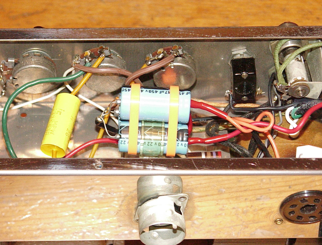
 This will only work if you have fairly small
caps. It works well with Xicons, if you are
staying with the original cap values of 10, 10
and 20uF. Pry up the cap clamp, and open it
up a bit. Clip the old cap wires (right by
the cap) and twist/push/pull the old cap out.
Bend the clamp as necessary, get the new caps
in, and bend it back down to tighten it up on
the new caps. Don't overdo this and deform
the cap shells! Add a cable tie on either side
of the clamp, snug against the clamp. Connect
the old cap leads as described in #1. In the photo
on the right (of a Gibson GA-8T) the (plastic)
strap is too small for all the caps, so it just
goes around the 22uF cap (the others in the
photo are 47uF).
This will only work if you have fairly small
caps. It works well with Xicons, if you are
staying with the original cap values of 10, 10
and 20uF. Pry up the cap clamp, and open it
up a bit. Clip the old cap wires (right by
the cap) and twist/push/pull the old cap out.
Bend the clamp as necessary, get the new caps
in, and bend it back down to tighten it up on
the new caps. Don't overdo this and deform
the cap shells! Add a cable tie on either side
of the clamp, snug against the clamp. Connect
the old cap leads as described in #1. In the photo
on the right (of a Gibson GA-8T) the (plastic)
strap is too small for all the caps, so it just
goes around the 22uF cap (the others in the
photo are 47uF).
- This will work with any cap that will fit
in the chassis/cab, even if you use three 47uF
Sprague Atoms. Drill out the rivet holding
the clamp. After clipping the cap leads (right
by the cap, of course) remove the cap and clamp.
Clean a 1/2" square spot on the chassis near
the empty rivet hole with steel wool. Use a
little acetone, and make sure you get all the
steel wool bits out (a shop vac works great).
This spot should be between the rivet hole and
the old cap leads. The new caps will be
centered over this spot. Attach a stick-on
cable tie holder
here.[1]
Run a cable tie through the holder, lay the caps across it, and fasten the tie. Add a tie around the caps at each end of the caps. Connect the old cap leads as described in #1.
- This is one of the few things I might buy at Radio Shack. Theirs stick fine, and unless you have a good electronics shop nearby, these can be tricky to find.
Last updated: 30 March 2006
Copyright Y2K Miles O'Neal, Austin, TX. All rights reserved. Miles O'Neal <roadkills.r.us@XYZZY.gmail.com> [remove the "XYZZY." to make things work!] c/o RNN / 1705 Oak Forest Dr / Round Rock, TX / 78681-1514