![[Front Panel]](Images/10-front.jpeg)
Control Panel (would be on top)
Control Panel (would be on top)
The gray plastic piece with the jack in it is the customer's home made, speaker out mounting plate.
This amp had been worked on. The PS caps had been replaced with a metal can cap inside the chassis (a short waiting to happen, in my book). A few other caps had been replaced, including the trem oscillator caps. The power tube cathode resistor bypass cap had not actually been replaced; a newer cap had been soldered in parallel with it. Not a great idea. Earlier tweed Gibsons were pure, flying lead, point to point, and a moderate pain to work on. As you can see here, Gibson was now taking a route similar to Fender's. This was still a minor pain to work on, though, as many leads and components blocked access to others. But at least everything was accessable from one side-- unlike with Fender's boards.
![[Guts]](Images/01-guts-ov.jpeg)
An Explorer's Guts Laid Bare
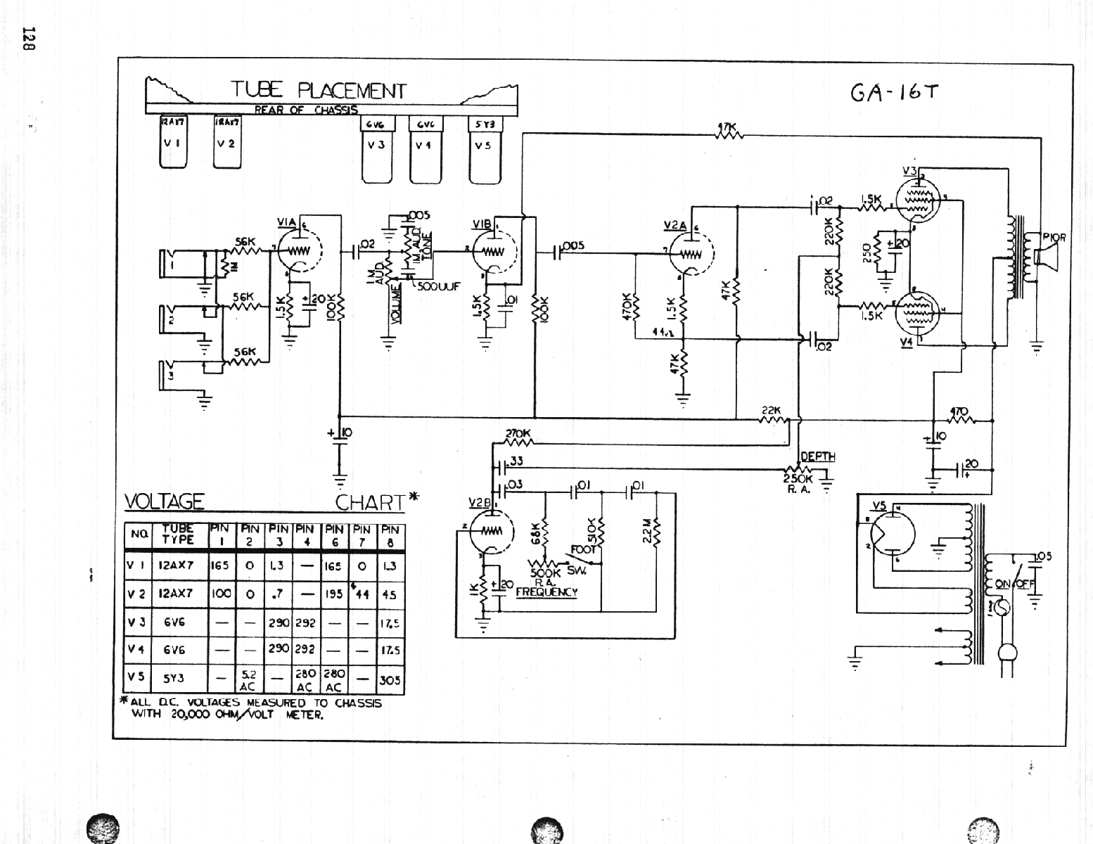
This amp has 2x12AX7, 2x6V6, a 5Y3 rectifier, a lacquered tweed cabinet, and a 10" speaker.
The owner complained of ghost notes. Replacing the PS caps and the power tube cathode resistor bypass caps took care of this. It turns out, however, that there are also intermodulation distortion problems. It probably needs a new OT; I'm awaiting the owner's decision on whether to send the amp back for this.
How does it sound? Much like a tweed Deluxe with slightly later breakup and tremolo. The tremolo sounds as good as I've heard with a simple circuit like this.
![[component board]](Images/02-comp-bd.jpeg) Component board closeup: A bit blurry,
but even so you can see that some of the ceramic
caps are under resistors, and others are over resistors.
Note the small guage, yellow jumper wires on the board.
You can get to everything without removing the board,
though some of the components would be difficult to work
with.
Component board closeup: A bit blurry,
but even so you can see that some of the ceramic
caps are under resistors, and others are over resistors.
Note the small guage, yellow jumper wires on the board.
You can get to everything without removing the board,
though some of the components would be difficult to work
with. |
![[power supply]](Images/03-power.jpeg) Power supply closeup: With the addition
of the three wire power cord, this is pretty standard
stuff. The original, multi-section electrolytic
(probably a brown "cigar" cap) has been replaced with
an Aerovox multisection, with the band crimped to hold
it in place. (I would have wrapped it in electrical
tape to avoid any chance of a short if the cap shifted.)
This cap was replaced with individual Xicons, as it had
leakage issues. You can't tell from this photo, but there
was also a black, ground wire that was just flopping
around at one end. Another short waiting to happen. I
used the loose end as part of the cap ground scheme, solving
that problem.
Power supply closeup: With the addition
of the three wire power cord, this is pretty standard
stuff. The original, multi-section electrolytic
(probably a brown "cigar" cap) has been replaced with
an Aerovox multisection, with the band crimped to hold
it in place. (I would have wrapped it in electrical
tape to avoid any chance of a short if the cap shifted.)
This cap was replaced with individual Xicons, as it had
leakage issues. You can't tell from this photo, but there
was also a black, ground wire that was just flopping
around at one end. Another short waiting to happen. I
used the loose end as part of the cap ground scheme, solving
that problem. |
![[octal sockets]](Images/04-pwr-sock.jpeg) Octal socket closeup: The sockets are on
the bottom side of the chassis when installed, which explains
all the dust and crud. This is baked on pretty well, but
doesn't poresent any problems. The socket at the left is
for the rectifier tube; the others are for the power tubes.
The big cap is the original cathode resistor bypass; the
smaller, gray cap is parallel. Both are 25V caps; I removed
these and used a 50V cap in their place. The resistors here
were fine, a pleasant surprise as they seemed to be
original.
Octal socket closeup: The sockets are on
the bottom side of the chassis when installed, which explains
all the dust and crud. This is baked on pretty well, but
doesn't poresent any problems. The socket at the left is
for the rectifier tube; the others are for the power tubes.
The big cap is the original cathode resistor bypass; the
smaller, gray cap is parallel. Both are 25V caps; I removed
these and used a 50V cap in their place. The resistors here
were fine, a pleasant surprise as they seemed to be
original. |
![[9 pin sockets]](Images/05-pre-sock.jpeg) 9 pin socket closeup: This is a bit blurry, but
there's not much that's exciting, anyway. It was nice that
Gibson stuck to the standard wiring color scheme here and
throughout.
9 pin socket closeup: This is a bit blurry, but
there's not much that's exciting, anyway. It was nice that
Gibson stuck to the standard wiring color scheme here and
throughout. |
![[inputs]](Images/06-input.jpeg) Input section: Note that Gibson didn't put any
resistors on the jacks. At the same time, they also didn't
put any on the preamp tube sockets; they're all on the
component board. While this is theoretically suboptimal,
in this case it didn't seem to cause any problems. But in
high RF areas, the first stage grid resistors and grid stoppers
might need to migrate to the tube socket.
Input section: Note that Gibson didn't put any
resistors on the jacks. At the same time, they also didn't
put any on the preamp tube sockets; they're all on the
component board. While this is theoretically suboptimal,
in this case it didn't seem to cause any problems. But in
high RF areas, the first stage grid resistors and grid stoppers
might need to migrate to the tube socket. |
![[control pots]](Images/07-controls.jpeg) Controls (pots): Note the judicious use of spaghetti
on bare component leads. I have no idea whether the zip cord
(lamp cord) to the tremolo pedal is original or not. It looked
old enough, but was in awfully good shape. You can see the new
trem caps someone added on the component board (baby blue and
yellow), just to the left of the fat, black cap.
Controls (pots): Note the judicious use of spaghetti
on bare component leads. I have no idea whether the zip cord
(lamp cord) to the tremolo pedal is original or not. It looked
old enough, but was in awfully good shape. You can see the new
trem caps someone added on the component board (baby blue and
yellow), just to the left of the fat, black cap. |
![[power controls]](Images/08-pwr-cont.jpeg) Power controls: Pretty much bog standard for
an amp of this era, other than the three wire power cord
someone added. Oddly enough, they left the death cap in
when they replaced the power cord. (That's the black cap
with the red stripe in the upper middle of the photo.)
The bakelite of the power switch was weak from age and heat;
when I started to desolder the death cap, it cracked. I
replaced it rather than risk it falling apart later in use.
Next time I'll just snip the stupid cap out!
Power controls: Pretty much bog standard for
an amp of this era, other than the three wire power cord
someone added. Oddly enough, they left the death cap in
when they replaced the power cord. (That's the black cap
with the red stripe in the upper middle of the photo.)
The bakelite of the power switch was weak from age and heat;
when I started to desolder the death cap, it cracked. I
replaced it rather than risk it falling apart later in use.
Next time I'll just snip the stupid cap out! |
![[transformers]](Images/09-trannies.jpeg) Transformers: I was concentrating on that horribly
small OT, and accidentally cropped the PT. The PT is about
normal size for an amp like this, which gives you an idea
how small that OT is (for reference, it's about the size of
the undersized OT on a 5W Kalamazoo Model 1 or 2).
Transformers: I was concentrating on that horribly
small OT, and accidentally cropped the PT. The PT is about
normal size for an amp like this, which gives you an idea
how small that OT is (for reference, it's about the size of
the undersized OT on a 5W Kalamazoo Model 1 or 2). |
ga18t-sm.gif 796x615 70Kb
ga18t.gif 1554x1200 434Kb
ga18t.jpeg 1554x1200 788Kb
ga18t.ps 771Kb
Copyright 2005 Miles O'Neal, Austin, TX. All rights reserved. Miles O'Neal <roadkills.r.us@XYZZY.gmail.com> [remove the "XYZZY." to make things work!] c/o RNN / 1705 Oak Forest Dr / Round Rock, TX / 78681-1514